Jk flip-flop: positive edge triggered and negative edge-triggered flip-flop D flip flop circuit diagram and truth table The d flip-flop (quickstart tutorial) d flip flop circuit diagram
Flip Flop Block Diagram - SR, JK, D, T, Master Slave - ETechnoG
Flip flop computer architecture sr input javatpoint organization clocked above figure D flip flop circuit using hef4013b Flip discrete flop circuit using transistors flops diagram hackaday explanation io
D flip-flop
D flip flop schematicD flip-flop circuit diagram: working & truth table explained D flip flop [explained] in detailD flip flop logic diagram.
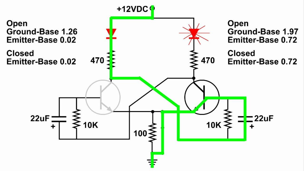
D flip flop logic diagramFlip flop explained electronics general What is a d flip-flop ??? (using discrete transistors)Flip flop circuit nand gates table truth input working diagram using type flops circuits output.

Flip flop flops jk circuits latches termed
Flop flip diagram circuit logic designing back topD flip-flop and edge-triggered d flip-flop with circuit diagram and [diagram] logic diagram of d flip flopCircuit design – cmos implementation of d flip-flop – valuable tech notes.
D flip flop circuit diagram and truth tableCircuit diagram of sr flip flop D flip flop circuit diagram and truth tableFlip flop led circuit diagram.

Flip-flop types, truth table, circuit, working, applications
D flip-flop circuit diagram: working & truth table explainedElectrical – circuit diagram for a d flip-flop with a reset switch Flip flop type edge triggered clock input flops output rs logic flipflop truth table schematic digital reset when if jkD flip-flop and edge-triggered d flip-flop with circuit diagram and.
D flip flop circuit diagram pdfFlip flop circuit logic explained delay detail Analysis of counter circuitsD flip flop explained in detail.

Flip flop truth circuit table symbol working diagram type flops clock inputs triggered explained circuits output
D flip flop design: from logic gates to circuit (diy guide!)Flip flop block diagram D flip-flopD flip-flop explained.
Flipflop: initiating d flip-flops (dff) in quartus: a guideEdge triggered d flip-flop circuit diagram Circuit diagram for d flip flopD flip flop circuit diagram and truth table.
.png)